What Is Optical Distribution Frame? Types & Uses Explained
By HENGXANG Firm · Published on September 30, 2026 · Updated on September 30, 2026
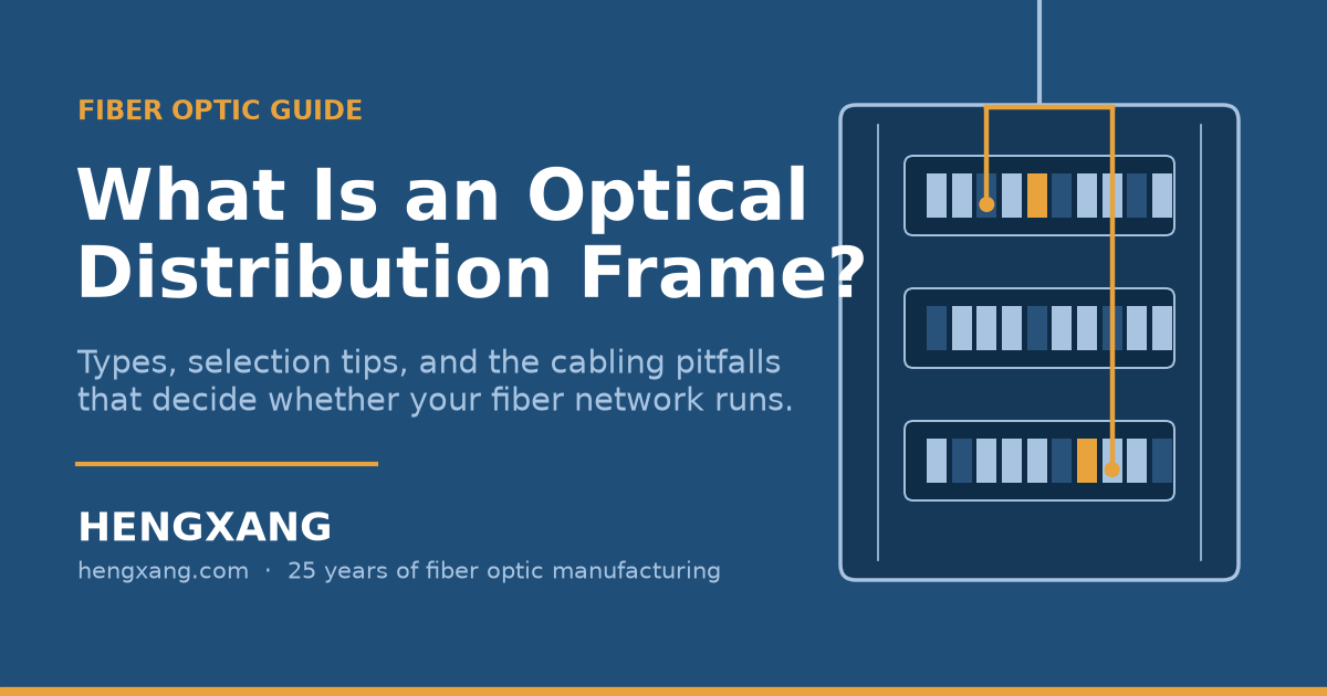
What is an optical distribution frame (ODF)? It is the rack-mounted steel frame, almost always sized for a standard 19-inch rack, where outside fiber cables terminate and connect to your network. Inside it, every incoming fiber is fusion-spliced to a pigtail, seated in a protected splice tray, and finished as a numbered adapter port on the front panel. Technicians then distribute, reroute, and schedule services by plugging patch cords between ports, never touching the cable itself. Capacities run from 24 cores in a small unit box to more than 1,152 cores in a full modular frame, which is why ODFs sit at the heart of telecom central offices, data centers, and building equipment rooms. Think of it as the master distribution box of a fiber network: light arrives on one side, organized ports leave on the other.
Anyone who has traced a mislabeled fiber through a ceiling at midnight knows the price of a badly organized one. The pain is never the frame itself. It is the missing label, the too-tight coil, the dust film on an unguarded connector. Good distribution design makes those nights disappear, and demand for it keeps climbing. One market study values the global ODF market at USD 1.36 billion in 2024, projected to reach $2.56 billion by 2033. Fiber is now the main carrier of information, from 5G towers to gigabit broadband to AI computing centers. The frame that manages all that fiber has quietly become mission critical.
We have manufactured fiber distribution equipment for 25 years from our factory in Jinhua, China. In that time we have shipped unit boxes, drawer panels, and full modular racks to distributors on every continent. This guide collects what we have learned, in plain language, so you can specify the right frame the first time.
What Is an Optical Distribution Frame?
An optical distribution frame (ODF) is a rack-mounted frame that terminates incoming fiber cables, protects their splices, and lets technicians connect or reroute lines with patch cords. Think of it as the master distribution box of a fiber network. Outside cables come in, tidy numbered ports go out, and routine changes never touch the cable itself.
Let's unpack that in everyday terms. An outdoor fiber cable enters your equipment room carrying dozens or hundreds of glass fibers. Those bare fibers cannot plug into anything. First they must be "terminated": each fiber is fusion-spliced to a short cable called a pigtail, and the pigtail's connector clicks into a standard port on the frame. Now you have a row of clean, numbered ports instead of a nest of glass.
From that moment, the frame becomes your switchboard. Need to move a customer from switch A to switch B? Run a patch cord between two ports on the frame. The FS.com guide to ODF basics describes this same idea: the frame is where fiber lines are connected, distributed, and scheduled. No re-pulling cable, no new splices, no downtime for the rest of the network.
A five-minute tour of one termination
Picture a 24-core outdoor cable arriving at an empty frame. The technician secures the cable at the frame's entry point and strips about a meter of outer jacket. The strength members get clamped first, so any pulling force lands on the armor, never on the glass.
Next, each buffered fiber enters a splice tray. The technician cleaves the fiber, fuses it to a pigtail, and slides a heat-shrink sleeve over the splice. A clean fusion splice adds less than 0.1 dB of loss, the level today's ODF guides treat as standard. Twenty-four splices later, the tray closes over all of them like a jewelry box. The pigtail connectors then click into the adapters on the front panel, one by one, until the row fills up.
Finally comes the step that decides your next five years: labeling. Each port gets a number that matches the splice record. Done well, the frame becomes a map of the network. Done badly, it becomes a puzzle box, and every future change starts with guesswork.
That is the entire magic of an ODF. Cable goes in, ports come out, and everything in between is protected, recorded, and repeatable.
Prefer to see it done? This 23-minute video splices a full 48-core panel from stripping and splicing to the finished, labeled ports: How to Splice Fiber Optic Patch Panel 48 Core
Most frames follow the standard 19-inch rack format, so they bolt into any standard cabinet or rack. That is the format you will see in carrier rooms and data centers. But it is not the only option. Smaller sites use wall-mounted frames, and desk-style boxes exist for labs and test benches. Form follows function: the more fibers you manage, the more the 19-inch rack wins.
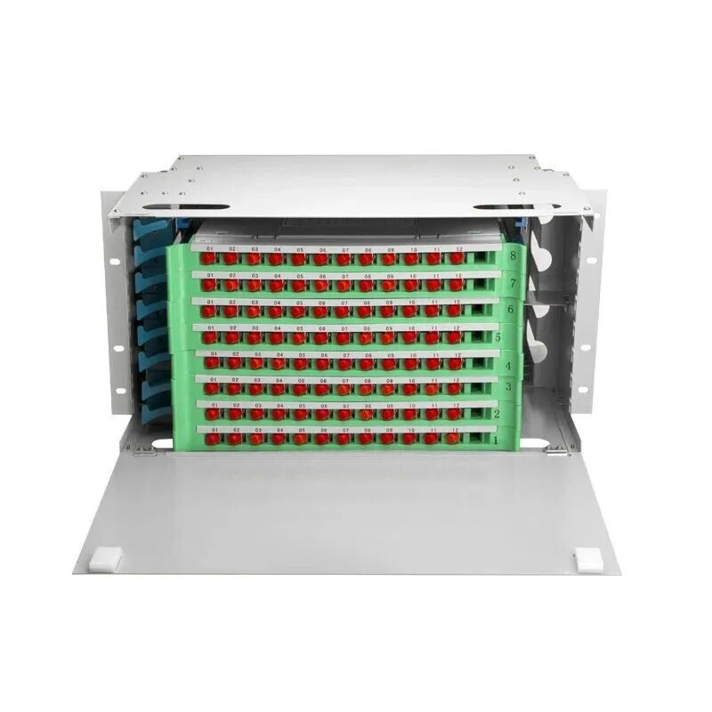
A 19-inch rack-mounted ODF with the drawer pulled out: numbered ports, splice protection, and slack spools in one unit.
Where does the ODF sit in the network? Between the outside plant and the active equipment. Outdoor cable comes in one side; switches, routers, and transceivers connect on the other. The frame is the meeting point, the demarcation, and the patching field all at once. Our optical distribution frames cover exactly this layer of the network.
One idea from our factory floor is worth keeping in mind. The ODF is a "silent" piece of the network: it carries no software and needs no configuration. Yet every single bit that enters your building passes through it. When a frame is well built and well organized, nobody notices it for years. That is the goal.
ODF vs fiber patch panel: the quick distinction
Searchers often mix the two products, so here is the distinction in one table. The panel serves one rack; the frame serves the building. In a large network, the ODF lands the backbone cables, then patch cords run from it to the smaller panels mounted next to each equipment rack.
| Point of comparison | Fiber patch panel | Optical distribution frame |
|---|---|---|
| Typical footprint | 1U to 6U box inside a server rack | Full 19-inch frame or cabinet, plus wall and floor options |
| Fiber count | 12 to 96+ ports | 24 to 1,152+ cores |
| Splicing | Rare; usually hosts pre-terminated cassettes | Core function, with splice trays and slack storage |
| Best environment | Closets, IDF rooms, individual racks | Central offices, data center halls, backbone entry rooms |
| Role | Organizes one rack's own fibers | Lands outside plant cables and feeds everything else |
What Does an Optical Distribution Frame Actually Do?
An ODF does three jobs. It terminates: each bare fiber is fusion-spliced to a pigtail and fixed to a standard adapter port. It distributes: patch cords jump between ports to assign or move services. It protects and stores: splices, slack, and connectors stay safe from stress, bends, and dust.
Job 1: Termination (creating port resources)
Termination is where raw cable becomes usable ports. The splicer fuses each fiber to a pigtail inside a splice tray, then heat-shrink sleeves protect every splice point. The pigtail connectors snap into adapters on the front panel. When the last connector clicks in, your cable has become a tidy bank of standard ports.
Why does this matter? Because ports are reusable and cable is not. Once fibers are terminated on the frame, every future change happens at the port, with a patch cord, in seconds. The splice itself never gets touched again. That single design choice is what makes fiber networks maintainable at scale.
Job 2: Distribution and scheduling
Distribution is the day-to-day work of a live network. A new tenant needs service on floor 12. A customer upgrades from 1G to 10G. A link fails and traffic must move now. In each case, the fix is a patch cord between two adapter ports on the frame.
Scheduling is distribution over time. Port 24 was customer A, now it is customer B. The frame's patch records, when labels are honest, tell the whole story of who connects where. Carriers live and die by this ability to reassign circuits without construction work.
Here is a concrete example. A carrier frame carries 576 terminated ports for a business district. On Monday, a tenant upgrades from one 1G circuit to two 10G circuits. Nothing is re-spliced and nothing is re-pulled. The technician moves two patch cords on the frame, updates the port record, and closes the door. Total work: five minutes. Without the frame, that same change means new cable pulls through occupied conduit, fresh splices, and a maintenance window booked weeks in advance.
Job 3: Protection and storage
The third job is the one buyers overlook, then pay for later. A good frame protects the weakest points in your link: splices, connectors, and bend-sensitive slack fiber. Splice trays hold the fusion points. Storage reels coil spare fiber at a safe radius. Dust caps and doors keep connectors clean. Cable rings guide patch cords so nothing sags, pinches, or rubs.
Failures we hear about from distributors almost always trace back to a missing protection feature. A connector left bare in a dusty room collects an invisible film, and that film costs decibels. A slack fiber coiled too tightly bends the glass, and bent glass leaks light. Protection is not a luxury feature on an ODF. It is the reason the frame exists.
The parts list
A complete ODF is built from a short list of parts, and each one has a job:
- Frame or cabinet: the steel body that mounts in the rack and holds everything else.
- Splice trays (fusion trays): protect the splices between cable fibers and pigtails.
- Adapters (couplers): the front-panel ports where connectors meet. Common types are SC, LC, FC, and ST, plus MPO/MTP for high-density rooms.
- Pigtails: short factory-terminated cables spliced to the incoming fibers.
- Patch cords (jumpers): the cables technicians plug between ports.
- Cable management rings and guides: route cords so they never exceed the bend radius.
- Labels: the cheapest part on the frame and the one that saves the most time.
The adapter choice matters more than buyers expect, because it locks in your connector family. Our fiber optic adapters page shows the SC and LC types most rooms standardize on. Data centers push this further: because their port counts are extreme, they favor the small LC interface or full MPO pre-terminated systems, where one connector carries 8, 12, or 24 fibers at once.
There is a hidden quality variable inside every adapter: the polish of the connectors it hosts. Two frames can look identical in photos and measure completely different in insertion loss. Our factory polishes connector end faces in a cleanroom and verifies every batch with in-line interferometer checks, because quality in fiber optics is decided at the micron level. When you compare frames, ask the vendor for the insertion loss and return loss numbers behind the adapter panel, not just the port count.
Two neighboring products often work alongside the frame. Outdoor cables usually get spliced and sealed in fiber optic splice closures before their fibers ever reach the indoor frame. And the pigtails and patch cords that make the whole system patchable are a product category of their own. Buy them from the same factory as the frame and the geometry always matches.
What Is an Optical-Digital Hybrid Distribution Frame?
An optical-digital hybrid distribution frame combines an ODF, a digital distribution frame (DDF) for copper circuits, and a power distribution unit in one cabinet. It exists because small sites run fiber and copper side by side. One hybrid frame replaces two racks and cuts cabling clutter in compact rooms.
Here is the real-world problem it solves. A fiber-to-the-building basement, a remote module station, a wireless base station site: all of them carry both fiber backhaul and copper E1 or data circuits, plus equipment that needs clean power. Installing a separate ODF rack, a separate DDF rack, and a power unit eats floor space these rooms simply do not have.
If the term DDF is new to you, here is the quick version. A digital distribution frame is the copper twin of the ODF: a frame where E1 or data circuits land on coax or twisted-pair connectors and get cross-connected the same way fiber ports do. Older buildings are full of them. The hybrid design simply refuses to pretend the copper world is gone, and gives both media a disciplined home in one structure.
The hybrid frame stacks all three functions into one structure. Fiber termination lives in its section. The digital distribution section lands the copper circuits. A built-in power distribution unit feeds the active equipment nearby. The result is fewer cabinets, shorter cable runs, and one place to stand when something needs attention.
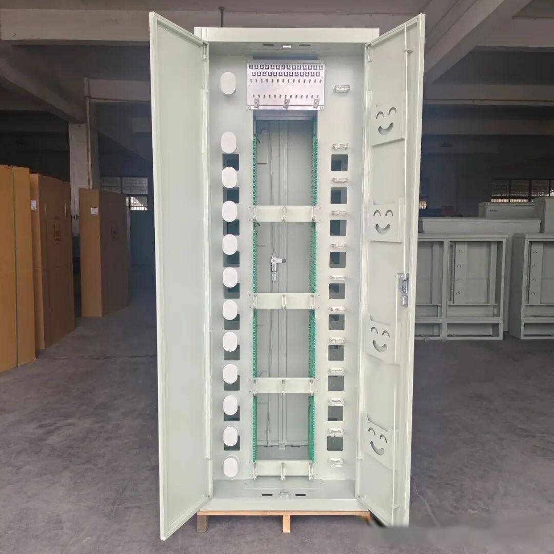
A hybrid optical-digital distribution frame: fiber, copper, and power share one cabinet.
Hybrid frames shine in what engineers call small and medium distribution systems. That includes fiber-to-the-neighborhood cabinets, fiber-to-the-building rooms, remote subscriber modules, and base station shelters. If your site fits one of those labels and space is tight, the hybrid design earns its keep.
When is a hybrid the wrong call? When your fiber count is growing fast. A dedicated ODF scales cleaner, and serious fiber density deserves a serious frame. For light-duty rooms, a wall-mount fiber termination box often does the same job as a small frame. For passive splitting points in FTTH networks, fiber optic splitters pair with small boxes instead of full racks. Match the hardware to the site, not to the catalog.
What Are the Main Types of Optical Distribution Frames?
The three classic structures are unit-type, drawer-type, and module-type. Unit-type frames are simple and cheap but force you to work inside the rack. Drawer-type frames pull out so each unit can be serviced in open air; they are today's mainstream. Module-type frames mix functional modules in one rack and trade the highest cost for the most flexibility.
Structural classification matters because it decides how maintenance feels in year three. Splicing and re-patching are hands-on work. Who does that work, in how much space, decides which structure you should buy.
Unit-type ODF
The unit-type design mounts several independent units into one rack. Each unit is a complete miniature distribution frame. Engineers describe it as preserving the features of small and medium ODFs while using the rack structure to raise space efficiency. It was the common early structure for large-capacity frames.
Its strength is simplicity. Fewer moving parts, lower cost, and a structure any technician can understand in a minute. For small and medium capacity, and in older equipment rooms, unit-type frames still do honest work.
Its weakness is the work itself. Splicing and re-patching happen inside the rack, where arm room is limited and neighboring units are always in the way. As fiber counts grew, that inconvenience turned into a real productivity problem, which is exactly what pushed the market toward the next design.
Drawer-type ODF
The drawer-type design divides the rack into units too, but each unit holds one or two drawers that slide out. To splice or re-patch, you pull the drawer out and work in open air in front of the rack. Each unit is independent, so touching one never disturbs its neighbors.
The details are where the quality lives. Good drawers slide on rails, lock in both the pulled-out and pushed-in positions, and hold their position under load. Those locks keep the operation stable and precise, and they keep the connectors inside safe from accidental bumps. The UNITEK Fiber ODF guide describes this as the sliding structure's core advantage: front-side operation without opening the whole rack.
This is the most widely used structure today, and our production numbers agree. When distributors order panels for general purpose rooms, they order drawers. Our sliding ODF for data centers is one example of the format at 6 to 48 ports, and the 72-core distribution frame shows the same pull-out logic scaled up.
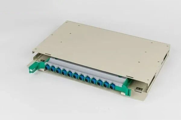
A drawer-type ODF unit with the cover open, showing trays and routing inside.
The honest limitation: storing and routing patch cords and pigtails around a moving drawer takes planning. Vendors solve it with rear cable managers and side rings, as the WeUnion Fiber type guide explains, but cord storage is still the drawer design's weakest point.
Module-type ODF
The module-type design splits the frame into separate functional modules. Cable splicing, distribution and patching, cord storage, and other operations each get their own module, and the modules combine in one shared rack. You compose the frame you need instead of accepting one fixed layout.
This structure delivers the most flexibility. Mainstream large-capacity modular frames use panel-and-drawer hybrid structures to make splicing and re-patching convenient, and they attack the cord storage problem directly with vertical cable troughs and an intermediate distribution layer. That intermediate layer is the trick: pigtails and cords get routed and stored in dedicated vertical channels instead of piling up in front of the ports.
The payoff shows up in large-capacity and high-standard environments, which is why module-type is the most popular choice for large frames in data centers. Global vendors reflect the same pattern: CommScope's ODF portfolio scales modular designs up to 864 fibers per frame. The cost is, well, cost. Module-type frames run noticeably more expensive than the other two structures.
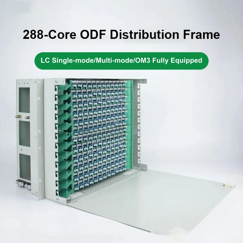
A 288-core high-density modular ODF of the kind now standard in large halls.
The three structures compared
| Structure | Main advantages | Main drawbacks | Best fit |
|---|---|---|---|
| Unit-type | Simple structure, lower cost | Work happens inside the rack; tight space; inconvenient to use | Small and medium capacity; older equipment rooms |
| Drawer-type | Work happens outside the rack; roomy; units do not affect each other | Cord and pigtail storage is average | Medium and large capacity; today's mainstream choice |
| Module-type | Most flexible; easy expansion; best pigtail management | Relatively high cost | Large capacity; data centers; high-standard sites |
Read the table as a decision path, not a ranking. Small room and light load: unit-type saves money. General purpose room: drawer-type is the safe default. Large fiber count, or a room that will grow: module-type pays back the premium in maintenance hours saved.
Two more inputs belong in that decision: who maintains the frame, and how often. If your team opens the frame weekly, buy the convenience of drawers or modules; the labor savings compound fast. If the frame will be touched once a year, a cheaper unit-type box does the same optical job. And if you serve carrier or colocation customers who audit their patching, the module-type intermediate distribution layer earns its premium in audit hours alone. Structure is a people decision disguised as a hardware decision.
The seven-question spec checklist
If you prefer a literal checklist, here is what we hand to our own OEM customers:
- Declared core count per rack unit, with margin for growth
- Minimum bend radius honored in trays and storage reels (30 mm or larger)
- Adapter type and polish grade, one connector family per frame
- Insertion loss and return loss figures for the mated connector path
- Dust protection: caps, doors, and sealed cable entries
- Grounding points and cable strength-member clamps
- Compliance statement naming the standard edition the frame meets
A vendor who answers all seven in writing is a vendor you can hold to the spec. A vendor who answers with a catalog photo is telling you something too.
How ODF Technology Is Evolving in 2026
The ODF looks like a steel box, so it is easy to assume it never changes. The opposite is true. Three forces are reshaping this product right now: density, intelligence, and standardization. Each one changes what you should buy this year.
Trend 1: Higher density
Computing rooms keep running out of ports, so frames keep packing more of them into the same space. One rack unit (1U) is only 1.75 inches (44.45 mm) tall, yet a 1U panel that once held 12 fibers now holds 144 or more. Classic LC panels pack up to 48 ports in that same height, and at the top end vendor frames scale from 24 to more than 1,152 cores in one cabinet. Three techniques drive the jump: MPO/MTP pre-terminated systems that land 12 or 24 fibers per connector, compact LC interfaces, and finer module design.
The push comes from the top of the market. AI training clusters are driving what one industry guide calls AI-driven ultra-high-density connectivity. The same report sizes the global MTP/MPO connector market at $1.45 billion in 2025, with data centers capturing 65.2% of that revenue, nearly $945 million. When one vertical takes two thirds of a connector market, the frames that host those connectors adapt or die.
Industry statistics we track put the average fiber connection density of a single hyperscale computing rack at 288 cores, and the share of MPO-based high-density modular frames keeps rising in shipments. Our own order book tells the same story. Ten years ago the typical order was a 12-core unit box. Today it is a drawer panel or a cassette chassis, and the 19-inch 144-core ODF has become one of our standard export items.
If you are building for density, look at cassette-based designs. Our 3U MPO cassette chassis shows the pattern: MPO trunks land at the rear, LC ports face front, and a cassette swap upgrades a whole row in minutes. Pair it with factory-terminated MPO trunk cables and the install becomes plug-and-play instead of splice-and-pray. For the full picture of where AI-era connections are heading, our deep dive on rethinking fiber connections covers the connector level.
Trend 2: Intelligence
A traditional ODF is what carriers call a dumb device. It holds ports, but it knows nothing about them. Port status and patch cord relationships live in paper records or spreadsheets, maintained by hand, going quietly stale. When records and reality drift apart, every maintenance task starts with an archaeology dig.
The intelligent ODF, sometimes called an electronic distribution frame, fixes the record problem at the source. Each port carries an electronic tag and a sensor. The frame detects which ports are occupied, logs every patch cord change automatically, and reports status over the network with SNMP. Remote management means one console shows fiber circuits across an entire city instead of one room at a time.
This is not a lab concept; carriers run it at scale. Huawei's carrier ODF line, part of its intelligent ODN portfolio, includes floor-standing frames that manage hundreds of cores per cabinet under remote management. For large data centers, the payoff is lower operations cost and an end to the "unknown port" problem during audits and fault tracing.
The measurable wins are specific. Smart frames locate a fault to the exact port instead of a rack, cutting mean time to repair. They expose idle ports, so capacity gets reused instead of bought twice. And because every patch change is logged, audits that once needed a surveying crew become a report download. In facilities with tens of thousands of cores, that is the difference between knowing your network and guessing about it.
Should everyone buy smart frames? No. The electronics add cost, and in a 24-core equipment closet they will never pay back. In large facilities where labor is the expensive part, automatic records and remote visibility change the maintenance math completely.
Trend 3: Standardization
Standards keep the ecosystem honest, and the governing Chinese standard just changed. In June 2026, the Ministry of Industry and Information Technology issued YD/T 778-2026, the new edition of the optical distribution frame industry standard. It replaces YD/T 778-2011 and takes effect on December 1, 2026.
The new edition refines the product classification, structural requirements, performance targets, and test methods for ODFs. For buyers, the practical move is simple: when you source frames during this transition, ask the vendor which edition the product complies with. Frames certified to the 2011 edition will not vanish overnight, but new projects should specify the 2026 requirements.
Standards also protect you at the rack level. A frame that meets the standard mounts in a true 19-inch rack, holds its declared core count, and passes the insertion loss and return loss tests it claims. That is the difference between buying steel and buying a distribution frame.
What Should You Look for When Selecting an Optical Distribution Frame?
Judge any ODF on five things: slack storage that keeps bend radius above 30 millimeters, solid protection for connectors and splices, room to add ports later, density that fits your space, and compliance with standards using one connector family. Miss one and the frame gets expensive after year one.
Selection is where specifications meet your actual room. The five criteria below come straight from what we see working and failing in the field. Use them as a checklist on your next purchase order.
Criterion 1: Cable slack storage and coiling design
Start with slack. The frame should hold a reserve length of the incoming cable, coiled and fixed inside the splice tray or storage reel. Plan on storing 1 to 2 meters of reserve per cable entry, which is the range modern ODF guides recommend. That coil is a buffer: it stops an accidental pull on the cable from reaching the splices, and it keeps stress off the fibers.
The number that matters most is bend radius. Coiled fiber must never bend tighter than the cable's minimum allowed radius. As a rule of thumb, keep storage coils at 30 millimeters or larger, and always defer to the cable's own datasheet. Coil tighter than that and you add bending loss that quietly eats your link budget, sometimes months after installation.
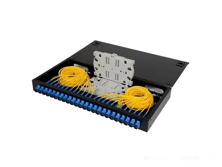
Splice trays and coiled pigtails: correct slack storage protects the bend radius.
Criterion 2: Protection performance
The frame is the bodyguard for your connectors and splices. Look for dust caps on unused ports, dust doors over adapter panels, and protective routing for patch cords. Splices should sit in trays with heat-shrink protection on every point. Match the enclosure rating to the room: IP20 dust protection for clean indoor rooms, IP65 or IP66 where moisture and weather get involved. And ask about adapter durability; quality couplers are rated for more than 1,000 plug-unplug cycles.
Why the obsession with dust? A connector end face is polished glass. An invisible dust film on that glass scatters light, raises insertion loss, and can even damage a transmitter at high power. A door that costs a few dollars prevents a fault that costs a service visit. Protection features are the cheapest reliability you will ever buy.
Criterion 3: Adaptability and expansion
Networks only grow. The frame you buy should let you remove existing connectors and add new ones, port by port, without rebuilding anything. It must also store and identify spare bare fibers: the ones from your trunk cable that are reserved but not yet connectorized. If those spare fibers have nowhere safe to live, your expansion capacity is fiction.
Our practical advice: buy 30 to 50 percent more port capacity than today's count. Empty ports are cheap. Full frames with waiting customers are not. When every port is occupied and a new service order arrives, someone is about to have a bad week.
Criterion 4: Density and space
Equipment room space is some of the most expensive real estate you will ever fill. Match frame density to the room honestly. A small room with simple needs does fine with 12-core or 24-core unit boxes. A large carrier room or data center hall should use high-density modular frames to save cabinet space.
This is also a budget decision. High-density frames cost more per port upfront but save racks, floor tiles, and cooling. Over a ten-year life, the dense frame usually wins in any room that will grow. Count your ports, count your racks, and remember that network cabinets and racks themselves are part of the space bill.
Criterion 5: Compatibility and standards
Finally, insist on products that meet the industry standards, such as the YD/T 778 series, and that mount in standard 19-inch racks. Standards compliance is your proof the frame was tested, not just photographed. It also means any vendor's cabinet can hold it.
Keep one connector family per frame. All SC or all LC, chosen once, applied everywhere. Mixing connector types on one panel forces hybrid adapters and offsets that add loss and confusion. And match the fiber itself: single-mode frames for single-mode systems, multimode for multimode. Mismatches create extra loss and maintenance chaos that no label can fix.
What Are the Most Common Structured Cabling Mistakes?
Eight mistakes show up again and again: wiring voice and data separately, running cable near interference sources, skipping forward planning, not labeling runs, laying cable parallel to power lines, ignoring distance limits, skipping certification tests, and stacking switches without a plan. Each one is cheap to avoid and costly to fix.
The frame sits inside a bigger system called structured cabling, and that system fails in predictable ways. These eight pitfalls come from engineering practice, and every one of them is preventable with planning. Note how many are about process, not product: even perfect hardware cannot save a bad plan.
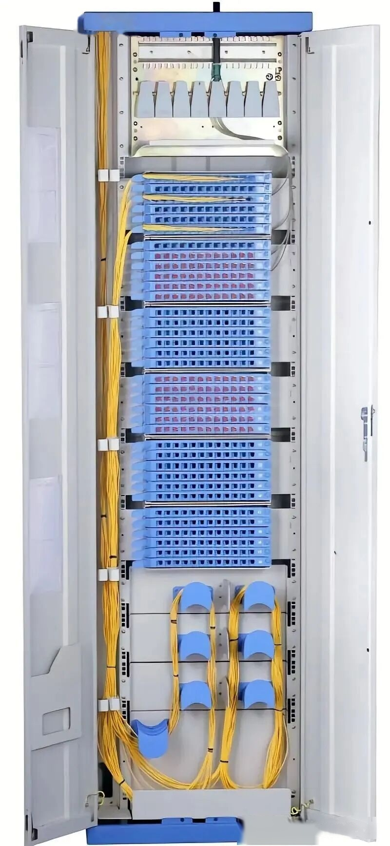
A well-organized ODF installation: labeled panels, guided cords, disciplined slack. This is what the eight habits below protect.
Mistake 1: Wiring voice and data separately
Old habit: run cheap Category 3 cable for telephones and better Category 5+ cable for data. It saved money once. It does not anymore, because voice moved onto the data network. With VoIP phone systems, a phone is just another Ethernet device that can take power through the switch port using PoE.
So do not assume voice needs its own cheaper cabling. Use the data network for both, with PoE switches powering the handsets. If a project truly requires separate voice lines, give them the same grade as the data runs. Anything less forces a re-pull the day the phone system upgrades.
Mistake 2: Running data cable next to interference sources
People assume only power cables interfere with network cable. In reality, fluorescent lighting, electric motors, variable frequency drives, and anything generating strong electric or magnetic fields will degrade twisted pair transmission. The interference is invisible until packets start retransmitting.
Keep data runs away from these sources. When distance is unavoidable, use shielded twisted pair with proper grounding, or isolate the path with metal cable trays and conduit. Shielding without grounding does nothing, so finish the job.
Mistake 3: No forward planning
A horizontal cabling link is designed to live 15 years or more, far longer than any switch it connects. Gigabit is everywhere and 10 Gigabit is entering ordinary offices. Choosing yesterday's cable grade to save a little today means tearing walls open when the upgrade arrives.
Our advice: install Category 6 or 6A for horizontal runs, and run fiber for backbones. The initial cost is slightly higher, but the cabling outlives several generations of equipment. Nobody has ever complained that their cable was too good.
Mistake 4: No cable management
Adding more cables does not help if nobody can find anything. Ladder racks and rack-based management cost money at install time and save enormous time at maintenance time. And management does not end at project acceptance: as runs multiply, disorder grows on its own.
The discipline that works is labeling. Label every run at both ends, color-code by system or by tenant, and update the records every time a cord moves. Years later, when a fault needs tracing at 2 a.m., the label is the difference between minutes and hours.
Mistake 5: Laying data cable parallel to power cable
Twisted pair survives interference because its two wires carry differential signals, and the twist cancels induced noise. But run unshielded cable parallel to a power feeder, and the magnetic field from the strong current overwhelms that defense. Symptoms look like mystery: slow throughput, retransmissions, garbage data, and in bad cases total link failure.
Keep parallel runs of data and power at least 300 millimeters apart. Where spacing is impossible, add a metal divider barrier or use shielded cable. Crossing power at 90 degrees is fine; running alongside it for meters is the killer.
Mistake 6: Ignoring distance limits
Before you pull any cable, confirm the distances you actually need. Copper Ethernet has a hard ceiling: 100 meters for the channel, built from 90 meters of horizontal cable plus 10 meters of patch cords. Need 10 Gigabit over copper near that limit? Category 6A or better is mandatory. Past 100 meters, copper is done.
That is where fiber takes over. The international cabling standard ISO/IEC 11801 sorts fiber channels into classes OF-300, OF-500, and OF-2000, each rated for application lengths of at least 300, 500, and 2,000 meters (a summary of the classes is maintained on Wikipedia). Chinese engineers meet the same structure in GB 50311-2016. If your building spans floors or campuses, plan on indoor and outdoor fiber cables for the backbone and copper only for the last horizontal hop.
Mistake 7: Skipping the tests
Cabling that looks finished is not finished until it is tested. Every link should be measured for transmission length, cable spec match, near-end crosstalk, attenuation, and return loss. Gigabit and 10 Gigabit networks need certification testing at their grade, with reports saved from a professional tester.
Keep those reports. They are your baseline for every future fault hunt, and your proof of quality at handover. Untested links pass at first and fail slowly, which is the worst possible schedule. The data supports the paranoia: in its 2025 Annual Outage Analysis, the Uptime Institute reports human error remains a leading driver of outages, with the share caused by skipping procedures rising ten percentage points in a single year.
Mistake 8: Adding switches without a plan
The last mistake is creep. More devices arrive, so someone plugs in a mini switch. Then another. Each one adds an undocumented hop, and each hop adds latency, failure points, and topology that nobody can draw.
As ports multiply, broadcast storms and bandwidth bottlenecks appear in places nobody expected. If a new service needs real bandwidth, the answer is planned new cabling back to the main frame, not a chain of improvised switches. When switch stacking is truly necessary, plan it: count the traffic, count the ports, and document the result.
Notice the pattern across all eight mistakes: every fix costs less before installation than after. The industry wraps this discipline in three habits worth memorizing: plan before you pull, label to the port, and test before you accept. Those habits, plus a properly specified frame, are the entire craft of structured cabling. Engineers who follow them enjoy quiet careers. The ones who skip them meet their cabling again, always at the worst possible hour.
To see the whole discipline in the field, this 40-minute documentary follows a real 900-foot underground build from trench to splicing to termination: 900ft Fiber Optic Full Installation Underground Fusion Splice
Conclusion
Three ideas survive from everything above. First, match the structure to the room: unit-type for simple small installs, drawer-type as the mainstream default, module-type when capacity and standards run high. Second, buy for the network you will have, with spare ports, real bend radius control, and one connector family. Third, respect the cabling process, because planning, labeling, and testing are what keep a fiber network boring in the best way.
The original question, what is optical distribution frame hardware really for, now has a plain answer: it turns raw cable into a network you can actually run. A distribution frame is steel, trays, and adapters, but its real job is turning cable chaos into numbered ports you can trust for a decade. Choose it with the same care you give your switches.
If you want a second opinion on your next project, send us your floor plan and fiber counts through the inquiry form at the bottom of this page. Our engineering team will recommend a frame configuration, connector plan, and capacity margin for your room. We have been building these systems for 25 years, and the first consultation costs nothing.
Frequently Asked Questions
What is an optical distribution frame in simple terms?
An optical distribution frame is the master connection box of a fiber network. Outside fiber cables enter it, get spliced to pigtails, and end up as clean numbered ports. Technicians then connect or reroute services by plugging patch cords between those ports, without ever touching the cables themselves. Most frames mount in standard 19-inch racks, following the format described in the FS.com ODF guide.
Is an optical distribution frame the same as a fiber patch panel?
The two terms overlap, but scale separates them. A patch panel is usually a small 1U to 6U box that terminates and organizes a modest number of fibers, often in a server rack. An ODF is the larger frame system that terminates, splices, distributes, and stores high-count backbone cables in one place, and it often feeds those smaller panels. In practice, small rooms buy panels and carrier rooms buy frames, and both jobs exist in most large networks.
Where are optical distribution frames installed?
You will find them in telecom central offices, data centers, equipment rooms, campus main distribution frames, and FTTH splitter points. The frame always sits between the outside plant cables and the active equipment, so every circuit has one fixed, organized landing point. Wall-mounted and hybrid versions serve smaller rooms where a full rack will not fit.
How many fibers can an ODF hold?
A basic unit or drawer panel holds 12 to 48 fibers. Mainstream rack frames run 72 to 144 cores, like our 144-core 19-inch frame. Modular systems go far higher: CommScope's ODF portfolio reaches 864 fibers per frame. Density per rack unit keeps rising as MPO cassettes spread through AI-era data centers.
What makes an intelligent ODF different from a regular one?
An intelligent ODF adds electronic tags and sensors to every port, so the frame knows what is plugged in. It logs patch changes automatically, reports port status over SNMP, and supports remote management from one console. Products like Huawei's carrier ODF line show the concept at carrier scale. Regular frames are silent steel; smart frames keep their own records, which pays off in large facilities where manual documentation drifts from reality.
Specify your next ODF with confidence
Send us your floor plan and fiber counts through the inquiry form. Our engineering team will recommend the frame structure, connector plan, and capacity margin for your room, with factory pricing from a 25-year fiber optic manufacturer.
Send Your InquiryInterested in our products?
Get a Quote